New Van: Electrical System

Disclaimer:
The wire sizes and fuse/breaker sizes notated in this schematic are shown for reference only. It is up to you to determine these parameters based on your specific system. There are a number of different factors that go into wire and fuse sizing. Use the Blue Sea Systems Circuit Wizard to help calculate your system requirements.
To make things easier to understand, I’ve broken down each element of the system into sections:
Main DC Distribution
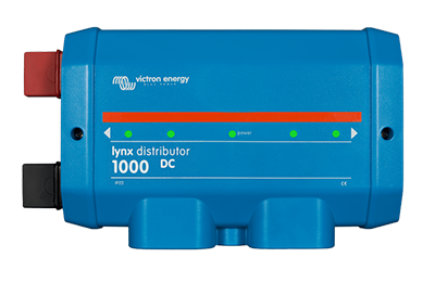
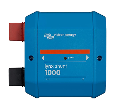
To handle power distribution we used the Victron Lynx system which is a set of fused bus bars with a battery shunt and main fuse. Because the lithium batteries we are using have an internal Battery Management System (BMS), we used the Lynx Shunt VE.Can as our shunt for this setup. Connected to the shunt we have two Lynx Distributors, one for battery connections and one for loads and chargers. Each distributor has 4 fused connection points. More can be added with the addition of an MRBF block or an additional Lynx Distributor. Using appropriately sized wire and MEGA fuses we connected the battery bank to the left of the shunt and all the loads and chargers to the right side of the shunt.

System Monitoring


The main control center for our electrical system is located in one of the overhead cabinets. Here we have our Color Control GX (CCGX) system monitor as well as the control unit for our Rixens heating system, breakers, shutoff, outlets, and mobile router. Having all the controls in one area inside the cabinet really helps keep things streamlined. The CCGX reads voltage info from the Shunt at the negative connection between the batteries and loads/chargers and communicates with the rest of the components in the system through various communication cables and displays all the system info on the screen. With the CCGX WiFi USB Module, we are also connected to our on-board WiFi so we can see and control our system from anywhere using Victron VRM.
For a more modest system design, you can just use a Lynx Distributor with a Victron BMV-712 or a SmartShunt.


DC Power Storage

For this build I wired each battery in the bank separately, each on its own circuit. This should provide more balance between the batteries as well as some redundancy in the case of a failure of any one of the batteries themselves. I made all of the cables for the positive and negative of each battery the exact same length. This helps to equalize the rate of charge and discharge of each battery in the bank. There are 4x 12v 100ah Battle Born LiFePo4 batteries wired with 2 AWG battery cable running to the Lynx Distributor on the left side of the Lynx Shunt. Each battery circuit is protected by a 125amp fuse on the Distributor.
Battle Born’s batteries have a max charge rate of 50A per battery and max continuous discharge rate of 100A. So from our 400AH battery bank, we can pull up to around 400A and charge at up to 200A. Be sure to take your specific battery specs into consideration when sizing your own system.

Solar Charging

Solaria PowerX-400R 400W Solar Panel
For passive charging we have a 400watt Solaria panel on the roof. This is a high quality, super efficient panel that’s a great size for the roof of a van. We almost tried to fit two of these up there but decided that we wanted to add a skylight with a little deck in that space. Mounting it lengthwise on the roof also allowed us to run deck boards along the sides of it giving us more roof access. We used an 8020 roof rack kit from DiyVan.com to mount this panel to our roof. We paired our 400W Solaria panel with the Victron MPPT 150/35 SmartSolar Charge Controller.


It’s important to provide a shut-off from the solar panel(s) to the batteries. We wired our panel through a 2-pole disconnect switch (positive and negative) before heading to the charge controller.
You will need a VE.Direct cable if you are using a Victron GX Monitoring Device such as the Color Control GX (CCGX) or Cerbo GX. Order a cable long enough to reach your GX device, with some extra slack. I was able to find a VE.Direct cable with a 90degree connector to better fit my installation.
Deployable Solar


Having the option to put out some extra solar panels is a great way to get extra power to our batteries while we’re stationary. Also, having the ability to angle panels toward the sun makes a big impact especially in the winter when the sun is low and the days are shorter.
We started with a 200W Renogy Solar Suitcase. This deployable solar kit is super easy to set up and it’s plug-and-play with its own built-in Voyager charge controller and alligator clips to connect to the battery system.

Recently we decided to upgrade to 400watts and found these smaller flexible 200W foldable panels. We paired these with a Victron 100/30 Charge Controller that we hardwired to our system in the electrical cabinet. These panels fold away and fit nicely behind our bed by the back doors.

Alternator Charging
Over the past few years living in a van we find that we tend to move around quite a bit. Getting power from the vans alternator has been crucial for us to keep a full charge.
For many years the Victron Orion Tr-Smart 12/12-30 has been the standard when it comes to DC-DC charging in a vehicle. This unit provides a max charge of around 30A. Initially we ran two of these units in parallel to produce ~60A of charge current when we drive. Since then Victron has released its new and improved DC-DC charger, the Orion XS 12-12/50. Operating at a 98.5% efficiency (5x more efficient!) this new charger packs more into a much smaller package and runs way cooler than its predecessor, so we decided to make the switch! Now with two 50A chargers we get 100A (1400W)!

These units run on a smart engine detect system that turns the charger on and off based on the voltage of the starter battery, so theres no need to run an ignition sensing wire.
Coming off the starter battery I connected a 2AWG positive wire to the fuse holder/bus bar on top of the starter battery using two square head bolts at the open terminal and a 150A MEGA fuse. The negative 2AWG wire is connected to the negative clamp terminal on the battery. From there I ran the wires underneath the van making sure to protect them from chafing and avoiding any heat sources. Then the wires enter the rear of the van through a cable boot in the floor where the wires land on a positive and negative terminal stud. From these terminals I ran 6AWG wire to each of the chargers with the positive wires being protected with 60A MRBF fuses. The common negative is connected from that negative terminal stud to the Lynx using the same size as the input wire (2AWG) via a short copper bus bar coming off the negative end stud of the Lynx. (This is also where the main system chassis ground (4/0AWG) wire is connected.) The positive output wires from the chargers connect to the Lynx via a dual MRBF fuse holder with 60A fuses on the positive end stud of the lynx.

Shore Power

We installed a 30A service plug through our rear bumper to connect to shore power. Although we don’t typically stay in campsites with hookups, it’s a great option when we need it. Before reaching our Victron Multiplus Inverter/Charger, the shore circuit runs through a 30A AC Main breaker for overcurrent and reverse polarity protection. With the Victron Multiplus, we can throttle the AC current input to whatever we’re getting from the pedestal/receptacle. This means we can plug directly into a 30A power pedestal at a campground or we can lower the current input and plug in to a 15A receptacle using a 15/30A adapter.

AC Loads
All of our AC loads are powered through our Victron Multiplus. While plugged into external AC power, the Multiplus with its PowerAssist feature can deliver over 50A of current. Although we will probably never use all that, I wanted to set it up to handle that capacity. From the AC-Out-1 connection on the Multiplus I ran 6AWG triplex wire to feed a 3 position circuit breaker subpanel. On that breaker panel we have 3x 15A circuits: one dedicated to our toaster oven, one for our induction cooktop and one that runs all of the other outlets in the van. Each circuit is wired first to a GFCI (Ground Fault Circuit Interrupter) receptacle with 14awg triplex wire. Any additional outlets that are wired off the GFCI outlets are also protected against ground faults. On the Multiplus there are two AC-Outs with the second being energized solely by shore power. This was a perfect place to wire up the electrical heating element of our heating system as it pulls up to 1500watts. I put that on its own 15A breaker.

DC Loads
All of the 12VDC loads in this system first come off the Lynx distributor through 2awg wire and a 100A fuse. That circuit feeds a 6 position 12VDC breaker panel. From there I wired up a few of our appliances directly: WATER PRESSURE (15A), REFRIGERATOR (15A), HEATER (20A)
Then with the remaining openings on the panel, I wired up three subpanels using fuse blocks that would each have their own branch circuits.
I wired in a 12-circuit fuse block for an ‘ACCESSORY’ subpanel using 8awg wire and a 40A breaker, a 6-circuit fuse block for a ‘LIGHTS’ subpanel using 12awg wire and a 15A breaker, and another 6-circuit fuse block to use as a ‘SPARE’ subpanel with 8awg wire and a 40A breaker. I wired the ’SPARE’ subpanel down below the bed so that anything that needed to be wired in at a later date would not need to snake up behind the wall to the control center in the overhead cabinet. Having a main breaker panel really helps to organize and control dc loads.
